This amp operates at very high voltages that can kill you. Do not attempt to build this amplifier unless you have already built several other amplifiers, preferably kits so that you can learn good techniques. I would highly recommend the Bottlehead kits. The exposed pins on top of the GK71s are a definite safety hazard. Do not use this tube if you have small children around, or even curious adults. Curious cats are also in danger.
For those of us who build amplifiers and have a few sitting around, there needs to be a good reason for building yet another amplifier. In this case, the reason was a mild heart attack which lead to a triple bypass operation on New Years Eve. Fortunately all went well and I have recovered quickly, probably because I do a three mile walk around my community about five times a week.
It's not a procedure that anyone would undertake just for the fun of it. Even with pain killing drugs, it's not entirely comfortable and lying in a hospital bed for most of the day gets boring. To help pass the time, I thought about building an amplifier. It's good mental exercise. My wife loaned me her Kindle Fire tablet and I was able to do some research.
I had a trip planned to India for five weeks in February which I realized would need to be postponed. The guidelines for recovery from bypass surgery include not carrying anything heavier than 7 to 8 pounds (4 kg) for quite a few weeks. Luggage becomes a real problem.
Moving boat anchor tube amplifiers also becomes a problem. So my thoughts turned to possibly building a reasonably powerful ( 10 watts ) amplifier that might weigh under ten pounds (5 kg) or so. Before all the health problems I had been thinking about building an amp based on a GM70, 813 or GK71 as the output tube. It looked like the GK71 was easier to drive than the others and could be operated at a lower plate voltage to achieve about 10 watts which would be adequate for my Tannoy 15" red speakers. Here are links to the GK71 datasheet and the GK71 triode curves.
To make this amplifier all directly heated, I decided to use the Russian 6S17K-V planar tube that I had enjoyed in a line stage I built a few years ago. Here is a link to the datasheet. This tube is actually indirectly heated but the cathode is connected to the heater which is somewhat unusual. In a topology sense, you could say it is semi-directly heated. It self biases with 6.3 vdc. It does not suffer at all from micro-phonics and gives a very clear sound.
If you decide to use this tube, read about the cooling requirements of this type of tube.
If you decide to use this tube, read about the cooling requirements of this type of tube.
The tiny 6S17K-V tube would not have enough oomph to drive a GK71 but I reckoned that it might work if I included Tubelab's Powerdrive. I had tried Powerdrive in my 6V6 amp and liked it. Although one of the reasons for implementing Powerdrive is to provide sufficient drive for the output tube to achieve class A2 operation, the other advantages are the elimination of the cathode bias capacitor and the ability to adjust the bias with a potentiometer.
So here is the schematic for the amplifier. Note that this is the original schematic and a later version is shown further down in the blog.


I had a couple of Edcore 8K:8 GXSE10-8-8K transformers from yet another failed project and crucially, the specs say that each can handle 100 ma but I will try to run them at 90-95 ma. If you are used to the concept of Powerdrive, there is nothing too unusual about this circuit other than I omitted the CCS to load the 6S17K-V because it is such a high mu tube to begin with and I wanted the filament bias to set the current, not a CCS.
So that is the easy part. The hard and usually heavy part of a direct heated transmission tube type amplifier is the B+ power supply and the heaters. The primary object of this amplifier is not to be the best 10 watt amplifier on the planet, but to be light weight. Great sound is allowed to be compromised in favour of reduced weight.
Let's look at B+. No doubt some of you have come across the Greenvalve GM70 website where Erick Bates uses a stack of Cisco 48v SMPS to get a B+ of 816 volts and a B- of -48 volts. Since my circuit called for about 500 - 600 volts and a B- of -200 volts, I figured I could use 12 @ 48 to get a B+ of 576 volts and 4 @ 48 to get a B- of -192 volts. Close enough. A vendor on Ebay was offering 16 of them for $99 including shipping so I ordered them.
Looking at the triode curves for the GK71, I am hoping for a bias point of 576 volts, 90 ma and about -80 volts bias. Hopefully these settings on the bias pots will be close enough to start with.
Looking at the triode curves for the GK71, I am hoping for a bias point of 576 volts, 90 ma and about -80 volts bias. Hopefully these settings on the bias pots will be close enough to start with.
Let's look at the GK71 heaters. 20 volts at 3 amps each and directly heated. This time I was inspired by Alex Kitic's use of electronic transformers for halogen bulbs in his 813 amplifier. He gave me some advice on the versions I should use for 110 volts and so I ordered a couple for about $20. This high frequency AC heating solution should weigh a whole lot less than a hefty transformer and the usual methods of implementing DC heating such as CLC or even the Rod Coleman solution.
In my original 6S17K-V linestage, I used a simple LM317 to get the 6.3 VDC for the heater. During my hospital research, I came across a DIY group in the UK called Audio Talk that created a group buy for a 6.3 VDC indirectly heated pcb. They published a schematic and that is what I used. They also had a thread for a similar direct heated pcb, but kept the schematic secret which is quite understandable. I figured the indirect version would probably do fine for the 0.3 amps required for the 6S17K-V tubes.
By the way, about ten years ago, I met Paul Barker ( he is a contributor to the group) at his house to listen to what I remember was an 833 amp. It was basically a bread board with clip leads everywhere along with an enormous power transformer. Unfortunately there was something wrong with the amp that day, but I was more than impressed by the outrageousness of it all. This hobby is meant to be fun and a bit over the top.
Incidentally, the Audio Talk had a thread on building a GK71 amp which was a mine of information from which I decided to use 5K transformers and the operating point.
Normally I would just use some strip board to do the Powerdrive and 6.3vdc circuits. Something changes after a triple bypass operation. You look at life a bit differently and I wanted to learn and experience more so I decided to lash out and create my first PCB using Express PCB. It seemed easy enough to do the Powerdrive circuit and I discovered I had enough room to include most of the 6.3 vdc circuit as well.
So all light weight components except for the two output transformers and a small 12 volt transformer to provide AC for the 6.3 vdc PCB.
So all light weight components except for the two output transformers and a small 12 volt transformer to provide AC for the 6.3 vdc PCB.

A Cisco 48 v @ 0.38 amps.
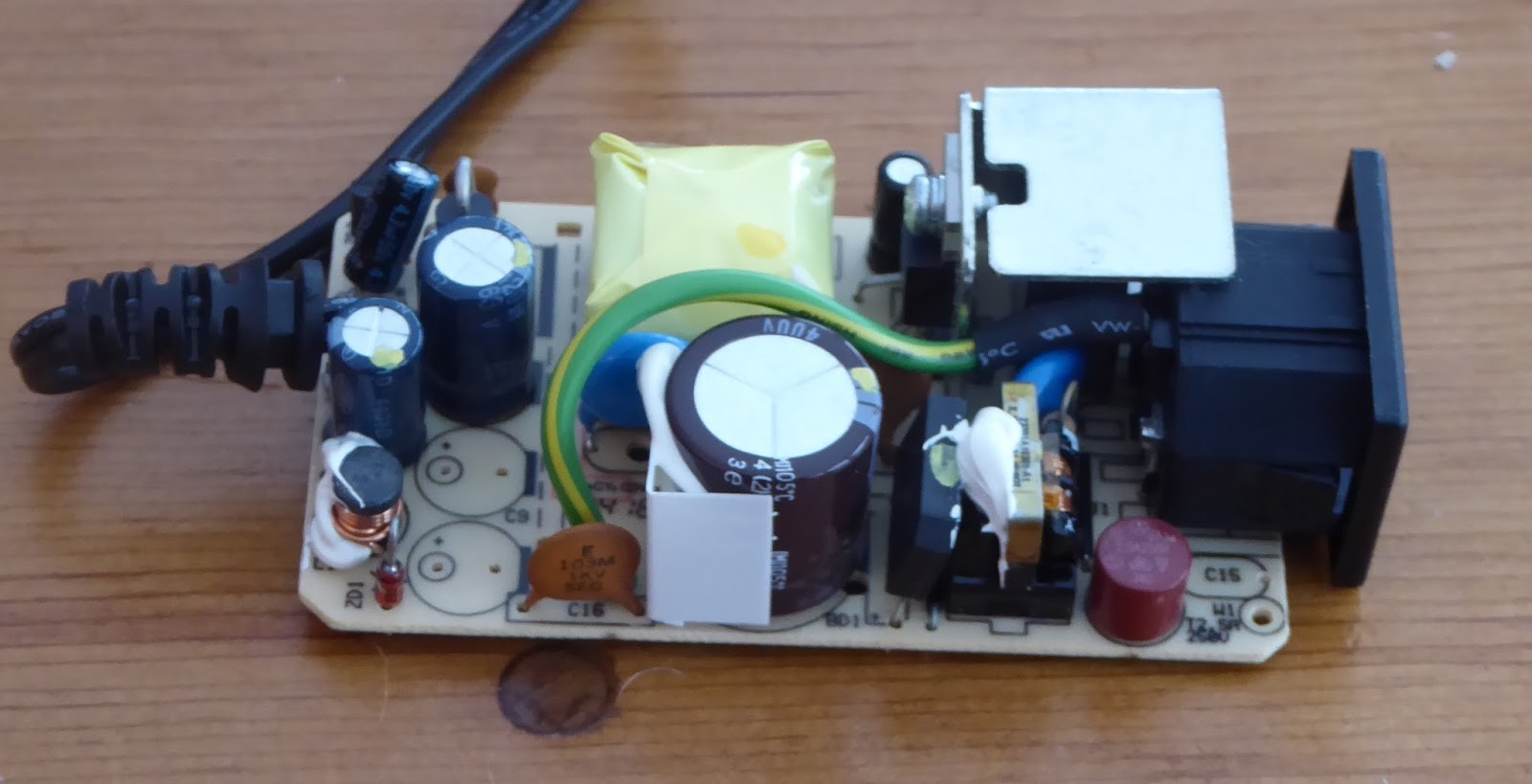
Case removed.

Backside. Each module is about 3.5" by 2".

IEC connector and ground wire removed. As I understand it, each module needs to float electrically so the ground connection should not be used.

Bank of four attached to a poly-carbonate sheet. The poly is just an 8 x 10 Lexan sheet from Home Depot cut in two. The poly should electrically insulate each bank of four modules from the next. Eventually I realized that the modules needed to be separated a bit more which was easy to do.

There was no convenient way to securely mount the modules so I drilled a hole in the metal heatsink and secured the module to the Lexan with a nut and bolt. Eventually I will make sure the nut does not loosen by applying a dab of nail polish.
Initially I will leave the wires long so that I can undo any mistakes. Later I can shorten them if the amp is successful.

The heavy items installed. One of the filament modules in the back to the right of the blue Edcore transformer. So far it weighs less than 12 pounds including the plywood.

Modified filament transformer with two extra turns (yellow) of 20 gauge wire which I added to the existing 12 turns. Two turns was not enough and I finished with 5 extra turns giving about 21 volts. I tried an extra 6 turns which resulted in 24 volts.
You could also remove the existing 12 turns and replace with 17 turns. The five extra turns took about 15 inches of wire.

This is a multimeter ( Extech EX205T) that can measure RMS AC. Whether it is accurate is another matter and eventually I will manage to get hold of one of the Flukes that can measure RMS AC or a scope which is the most accurate method. Incidentally, my Fluke 75 failed dismally recording only 9 volts but it cannot measure RMS AC.
I figure that if the AC voltage is in the 18 - 22 range, I will probably be ok. And a GK71 tube is very inexpensive at under $20.

The finished product. The capacitor is 560 uf 200 v and is an essential part of getting rid of any AC 200 hz buzz. Read more about it at Alex's web page. You will notice that for the 240 volt Europe you would use a 270 to 330 uf 400 v cap. I attached the cap to the plywood with a glue called Goop. I have used it extensively in the past, even with motor run caps. I also used it to attach the 0.1uf KSG silver mica coupling caps. The bond can be broken with some difficulty.
Warning note. After powering off, a 25 - 30 voltage remains in the caps. I will install a 1 meg bleeder resistor in my next version of the amp.
Alex left his versions inside the cases they came in which would be easy to mount. I left them outside to make it easier to get rid of any heat. I mounted them by screwing the T220 cases to the plywood.

As usual, I use the two DPDT switch method of delaying HT. The transformer on the left provides the filament power for the 6S17K-V tubes. Each 6S17K-V uses 0.3 amps.

Erick Bates used 4K 2watt resistors as a load for each module. I used 4.7K 2 watt resistors that were a lot cheaper. It was not too difficult to daisy chain the leads to the modules but it does get a bit fiddly and boring. I left the leads long at this stage and if the amp is successful, I will shorten them to fit better.
Be careful to ensure that you observe correct polarity as you daisy-chain the output wires together. On the modules I used, the negative wire was closest to the edge of the module but you should check this yourself. The positive wire had white printing.
In the next version of the amp I will raise the strip up a few inches to make it more accessible.

The PCB turned out good enough though I made one mistake that was easily bypassed. The DC regulator section is cramped but I was greedy. I did not have enough room for all of the components mentioned in the UK Audiotalk article so some of the larger capacitors are off the board. It was a fun exercise to do this and not all that difficult. Initially, the board produced about 6.9 vdc. Changing the 56 ohm resistor to 28 ohm reduced the voltage to 6.3.

Closeup of how I mount the tiny 6S17K-V planar tubes. The green wires are 12 gauge copper. No solder is used. The holes in the plywood behind each tube allow the heat to escape. Since they are metal they don't light up. However the advantage of the metal is very low micro-phonics.

Somebody asked me in my blog on the line-stage whether it is possible to solder wires to the metal parts of the tube. The answer is yes, but I would not be too confident about the joints.
Important! I have tried soldering the grid resistor to the tube and the tube stopped working. I suspect the tube is very heat sensitive so I have gone back to the original idea and two new tubes. Fortunately they are only $2 each. One slight change, I soldered the grid resistor to the end of the 12 gauge wire as close as possible to where the 12 gauge touches the tube. Just make sure the 12 gauge is not touching the tube when you solder.

The GK71 filament produces 60 watts ( 3A @ 20 v) which along with the plate dissipation of 55 watts is a lot of heat to get rid of. Even worse than my 6C33C amp. So I mounted the socket on the top side of the plywood and fed the connecting wires through a hole cut in the plywood.
The socket is seven pin similar to those used for 829B tubes but the GK71 pins are much thicker so a special socket is needed. The pin at the top of the tube is also thicker than those of an 829B.

Yes, it is a rats nest but I may do a second version to clean it up a bit. It will then look like there is only one rat in the nest instead of two.
The dual power switch arrangement makes testing easier. First establish that the 6.3 vdc and 20 vac boards are working ok. Before adjusting the Powerdrive potentiometer to establish the desired bias point ( -80 vdc approx), do not connect the cap to the GK71. Finally, connect the cap to the GK71 and make the final adjustment to the potentiometer to fine tune the current through the GK71. The dcr across the Edcore output transformer is 207 ohms so I aimed for somewhere between 18.6 volts for 90 ma and 19.6 for 95 ma. I finished up with 19.1 volts for 92 ma. Bias derived from the Powerdrive is -77 volts with a B+ of 577.
A 3 amp fuse is a bit marginal and I used a 6 amp that I had on hand.
I can't hear any hum so far.
My estimate of power output is about 10 watts based on the discussion by the UK Audio group about building a GK71 amp. It would be quite simple to drastically increase the power by adding another bank of 4 modules (16 x 48 = 768 volts) and substituting output transformers that can cope with higher current than the 100 ma of the Edcore transformers. The GK71 has a maximum dissipation of 125 watts which is much more than the 55 watts of the current design. Throw in the ability to operate in class A2 and this amp has the potential to be a real beast at lets say 768 volts at 150 ma per channel. I don't need that kind of power,but I might consider using more exotic output transformers at some stage.
The cost of building this amp has been quite low, for me less than $300.
16 x Cisco SMPS modules - $100
2 x halogen bulb electronic transformers - $20
2 x Edcore output transformers - $60
2 x GK71 tubes - $40
2 x GK71 sockets - $16
2 x 6S17K-V tubes - $4
2 x KSG 1uf silver mica caps - $10
1 x 12 volt transformer - $5
sundry resistors, semiconductors, wire, switches, IEC socket, RCA sockets, binding terminals
Of course, shipping adds to the cost, but $300 is a reasonable approximation. Three of the PCB boards cost about $50.
Better output transformers would add to the cost but there is not much else in parts that would drastically improve the sound quality of the amp. If I rebuild the amp, I would probably improve the grounding by using 12 gauge wire or a strip of copper as a bus bar and re-positioning the module boards so that the ground tap lies next to the 12 gauge wire.

The finished product. My wife is a very good quilter but she recognizes that despite her considerable abilities, she cannot attain the 'technically physically perfection' that others can achieve. Obviously the same applies to me. What you can't see in this photo are the washers that I install between the top piece of plywood and the wooden sides. They provide a narrow slit around the top and presumably increase ventilation.
The 6S17K-V tubes are mounted under the one inch holes just to the right of the RCA jacks. The holes allow for ventilation.
It would be relatively simple to substitute a GM70 for the GK71. The heater requirements are the same however you would need to provide a higher B+. Erick Bates used 720 vdc and a 6K output transformer. You could possibly use an 813 but the heater requirements are different and I would advise you to look at Alex Kitic's 813 project. The advantage of the GK71 is the lower B+.
I have no idea how safe these stacked modules are. Use them at your own risk.

Cat proof.
My speakers are 15" Tannoy reds that I use on an open baffle. The low bass is handled by 18" Goldwood 1858s powered by a digital amp. A PLLXO handles the crossover. Since the Tannoys are 15 ohm, I will eventually replace the output transformers with units with 16 and 8 ohm taps. The transformers can be smaller since they don't need to handle anything below 80 hz. I would probably look for transformers that could handle a bit more current.
As a side note, the Tannoys sound much better to my ears on an open baffle than in any box I have heard. The detail is incredible and I presume this is because the 15" cone is not having to do so much work handling the low frequencies and pushing against the air in a box. I inherited them from my father and never had the room for boxes that would be suitable. Now I will never put them in a box and I won't bother looking for other drivers.
Getting back to the amplifier and the object of the exercise, the weight of the various parts without the box turned out to be about 10 lb 8 oz (5kg). The plywood top weighs about 3 pounds and the sides about 4 lb 8 oz for a total of about 18 lb. That is pretty light weight for a direct heated transmitting tube stereo amp. The next challenge is to determine how to make the box less heavy. Perhaps I could cut large holes in the sides or use some lighter weight material. Anyhow, it has been a fun project.
No doubt, you want to know how it sounds. I used inexpensive speakers for a while before I tried the amp on the Tannoys. So far the results are impressive. The amp is quiet, no hum or buzz. This stacked SMPS and AC heating works. I am currently listening to Beethoven's Cello Sonata #2 with Steven and Carol Honinburg and the cello has a wonderful sound. The sound seems to be even more detailed than the 6C33C amp and the sound stage is deeper. Initially I thought the new amp was less dynamic but now it is just as dynamic as the 6C33C. More later as the amp breaks in but this amp is a definite keeper. Many thanks to all who provided the various ideas.
By the way, I have recovered very well from the surgery. I am back to doing my regular 5k walk around my community and I have a trip to Rome planned in late April. It was a very interesting trip with some wonderful gelati.
A followup. The amp is a bit too bright for my taste even though I hear more 'stuff' in familiar recordings than I do on other amps. I remembered that I had a pair of old 2.5 K Audio Note transformers each weighing over 20 pounds and I have arranged to run them outboard from the main amp. I use the 4 ohm taps on 8 ohm speakers and the 8 ohm taps on my 15 ohm Tannoys. And yes, they are better than the Edcores.
Another followup. I am currently rebuilding the amp using the Audio Note transformers. Hopefully the newer version will look a little less ugly.
______________________________________________________________________
Version 2 still looks just as ugly.

The Audio Note transformers have replaced the small Edcore transformers. Each weighs 22 pounds (10 kg). I have raised up the yellow terminal strip which connects the SMPS units to make it more accessible.
I reversed the direction of the yellow terminal strip and the high voltage tap is on the left. There is now space for an additional set of 4 SMPS units if I want to take the voltage up to 768 (48 x 16).
I have also raised the current to about 100 ma. I could go higher but there seems to be quite adequate power for my speakers.


The plastic assembly on top of the transformers has four of the ferrite core things that come with each SMPS unit. The +576, +192, -192 and +144 taps each pass through a ferrite.

The ferrite cores.

I have added a small fan to help cool the 6SK17-V tubes which tend to fade away if they get hot. The fan is very quiet and I don't notice it.

Closeup of the connection. Notice how I have soldered a carbon composition resistor to the thick wire that connects to the grid. Do not solder this connection while the thick wire is in contact with the tube. The heat might ruin it..
I have used a long piece of 14 gauge wire as a ground bus. You can see it to the right in the photo.


It all fits on an 18" x 18" frame.
The ferrites really helped calm the brightness which I suspect was some hash on the line. My oscilloscope has died so I can't prove this but the sound is much better and I really enjoy listening to the amp. It is incredibly dynamic and clear and has a deeper sound stage than any other amp I have built. It is one of those amps that makes you want to examine all your collection because recordings reveal more more.
_____________________________________________________
Version 3
Version 2 was too heavy to carry comfortably so I have gone back to the idea of taking the 22 pound Audio Note transformers off board and connected via plugs on top of the amp.

This is only temporary for testing. The layout inside remains much the same as version 2 but I have doubled up on the ferrites on the 576 vdc and 144 vdc outputs from the smps units. I think this has helped at the higher frequencies. I have also added a 16 uf motor run cap from the 576 vdc to ground and a 10 uf motor run capacitor for the 144 vdc to ground. This has reduced the brightness considerably and the amp now sounds much better. I might try different value caps since I just used what I had on hand.
I have also installed sheets of metal between the body of the amp and the output transformers which I have connected in outboard fashion.
I have also reduced the 2SK3964 drain voltage to +96 vdc which seems to work fine. I have added single ferrites to the +96 and -192 taps. I am thinking about adding motor run caps for the +96 and -192 taps.
Here is the latest version of the schematic. Note that the 20K resistor in the Powerdrive is now 10K (mistake on my part) and that about 11 ma is passing thought it.

The current is back to about 90 ma per channel since I don't really need to use 120ma.
I tried placing the AN transformers on top of the box but the radiation from the smps units causes mid range distortion which diminishes the further I keep the transformers from the smps units.
This amp has been a real journey and I expect to keep fiddling with it for some time. Interestingly, a long discussion has started on the Tube DIY Asylum about the high frequency AC heating in the December 2016. I have not yet made any of the suggested mods to increase the switching frequency but I may try it sometime.
The top is made from two pieces of laminated flooring from Lowes. If you try using that stuff, the only thing I have found that sticks to it is Gorilla Glue.
____________________
Update on version 3.
The amp was suffering from some distortion in the lower mid-range at high volumes that was not there in earlier versions. I eventually track down what had gone wrong. When removing the Powerdrive board, I had managed to break one of the legs of a 2SK3564. When I replaced it, one of the solder connections was less than stellar. Fixing the solder joint solved the problem.
I have played around trying to get rid of the exaggerated high frequencies. I removed the ferrites really were not helping all that much. However what did work was to installed a 45 uf motor run cap at the 576 vdc tap, a 16 uf motor run cap at the 144 vdc tap and 5.6 uf film caps at the +96 and -192 vc taps. These cut the high frequency exaggeration but also a bit of the sparkle, depth and detail. I then fitted a 6800 pf Russian silver mica capacitor across the 45 uf and 10 uf caps. These caps are 500 vdc rated which is less than my 576 vdc supply so I will have to see if they hold up, but I suspect they will. There is nothing scientific about the values I selected except that they are typically what I would use in similar positions in a normal power supply.
The sound is now getting to be pretty good. It's very dynamic, with the bite that makes recorded instruments sound more like real instruments and voices like real voices. The sound-stage is impressive with depth and the level of detail is the best I have achieved in my amplifier building. No doubt I will keep fiddling with it, but I think I am close to done.

So this is what happens when you subject a 500 vdc silver mica cap to 576 vdc. I had played the amp for about five hours and all was well, but I did not turn off the amp for a while and then there was a sharp bang. I may try two caps in series with each cap bypassed with a 1 meg resistor that can take 400 vdc. The amp is still working fine.
Another update on version 3.
Sometimes it takes me a while to decide if a change was worthwhile or not and eventually I decided that the lower mid-range felt a bit syrupy so I removed the 45 uf cap (and silver mica bypass) from the 576 connection to the output tubes and so far I prefer this arrangement. I have retained the 16 uf cap on the input tube.
By the way, there has been some more discussion about high frequency AC heating on the TubeDIY forum and it appears that those people who's hearing abilities extend well beyond the normal 20 khz limit may be able to hear the noise from this method of heating. My limit is 13 khz and I am not affected. YMMV.
This is great. I really love your page. The very creative use of weird objects is inspiring. How do you like the PowerDrive with the GM-71 at lower voltage? I am afraid of the kilovolt range. I have a couple GM-70s and might try to replicate your circuit. Thank you
ReplyDeletePowerdrive seems to work for me and I have used it in some other amps. One of the reasons why I picked the GK-71 was the recommendation from the Audio Talk group in the Uk that the GK-71 worked very well in the 500-600 volt range. By the way, Jim Dowdy runs his GM70 amps at 735 vdc so if you don't need the power, you don't need to go over 1000 vdc. If I were to modify this amp to run GM70s I would just add another 4 SMPS modules to give 768 vdc. I am scared of the kilovolt range as well.
ReplyDeleteI am still working on the amp and learning about what works so if you want to build something similar, wait a bit. My next step is shielding the SMPS units. Or perhaps you could just go ahead with a breadboard since the components are relatively inexpensive.
Nice circuit! It will go well with my K1. So is the matching input transformer just wound on a round toroid, if building it from scratch? Also would a blocking cap on the input (to keep DC out of the transceiver) be a bad idea?
ReplyDeletebest tube amplifier
This comment has been removed by a blog administrator.
ReplyDelete