When my mother-in-law died several years ago, we inherited her small ginger cat. We are primarily dog lovers, particularly Airedale Terriers. However, cats tend to like me even though I am relatively indifferent to them. Probably that is why they like me. Catty-watty is getting older and has a tendency to vomit. Since she likes to sit in warm places, amplifiers are attractive to her and she already has ruined the power supply of one old receiver with an appropriately placed dribble. While my wife would not be too upset if the cat disappeared in a puff of smoke, I am just an old softy. Consequently I have stopped using some of my tube amps, particularly those with top caps.

So here it is in all its glory, a tube amp designed to be cat vomit proof. The case is simply plywood, roughly 16" x 21" x 6". The cage on top is three wire cooling racks tied together with some wire to make a triangular shape.

The large tubes are the 6C33C output tubes. Those of you who are older might remember a Russian pilot defected to Japan in 1976 in a MIG fighter jet. The Japanese let the Americans examine the plane and they were puzzled that the Russians were still using tubes / valves in their planes. It turned out that the tubes were not effected by the electro magnetic pulse generated by a nuclear explosion. Ordinary solid state components would be effected or destroyed by the pulse. These are the same tubes used in the jet fighter. They cost about $16 each when you buy them from Russia or the former Soviet bloc countries. You might notice two large black resistors between the output tubes. These are 100 watt 1K ohm resistors that form the plate load for each tube in this parafeed design. The input / driver 6E5P tubes are close to the RCA input jacks.
The large aluminium bars are heat sinks for the 400 ohm bias resistors. They also serve as a base for the wire triangle.
These tubes and the resistors are putting out a combined 180 watts of heat approximately. This is too much heat to try to dissipate inside the chassis so I placed these items on top. The high voltage connections are covered with electricians tape,

Here is the schematic of the amplifier and except for the parafeed topology is fairly typical of 6E5P - 6C33C amplifiers. Most parafeed amps have a plate choke instead of a large resistor at R5. It's much less expensive to run at a higher B+ voltage and use a resistor instead. I got the idea from the Steve Bench web site. (see the third example, RC coupled)
I have used this topology quite a few times and I like the sound of it. I've even used light bulbs as the resistor and I reckon they sound 'better' than a straight resistor even though they are not as linear as a resistor. Think of them as a seasoning in cooking. I may yet try the amp with a couple of 50 watt Australian bulbs. Each bulb has an approximate resistance of 100 ohms.
P = V I
V = I R
R = V / I
R = V * V / P
250 x 250 / 50 = 1000
I've used Australian 50 watt bulbs with my 829B amp and also with my 6V6 Lumiere amp. You have a to fine tune a bit with a resistor in series. Generally the bulbs are a bit over 1K. The 'bulb sound' is present even with a normal resistor in series with the bulb. I suspect the 'bulb sound' is some sort of resonance that happens to appeal to my ears. It may not appeal to you.
The circuit is very basic otherwise with auto bias on the out put tubes. Some builders state that this output tube sounds better with fixed bias. They may well be correct but this tube is reputed to be finicky and liable to 'run away' and self destruct with fixed bias. Since this is the first time I have used this tube, I chose the safer route.
The CCS comes from Gary Pimm and is easily set to 15 ma. Other builders using the 6E5P have used 13 or 17 ma. I chose to use the halve the difference. Another possibility is a CCS using 4 DN2540 depletion mosfets.

The ceramic sockets for the 6C33C tubes are mounted with approximately one cm clearance to allow for any heat from inside the chassis to escape easily. I have not used any fans.
Since I was not sure how the 6C33C tube was going to behave, I installed meters to monitor the bias voltage which for this amp was supposed to be -80 volts. The operating point is 200 volts, 200 ma and -80 volts which reputedly produces about 14 watts per channel. On the other side of the amp is another similar meter that monitors the B+ at 480 volts.
Each meter is a 1 ma meter
http://www.allelectronics.com/make-a-store/item/pmd-1ma/1-ma-dc-panel-meter/1.html
For the bias meters I hook them up with a 100K resistor between the meter and the cathode of the 6C33C and the other side of the meter connects to ground. For the B+ I use the same meter but with a string of resistors that add up to 1 meg. I allow 100 to 150 volts for each resistor so in this case I just have five 200k resistors. The B+ meter reads approximately 48.
B+ is 480.
The drop over the 1K resistor is 200.
The drop over the plate is 200.
The bias is 80.

The power supply is the contraversial LSES supply that has been extensively argued over in the TubeDIY forum. I could have used the typical large 5 or 10 henry Hammond choke from my stash but the largest chokes can only take 300 ma. Because of space limitations in my listening area, I can't fit mono-blocks so I use a single B+ power supply that feeds both channels. Since two channels would need 400 ma, my Hammond chokes would not be usable. The C-56U and C-40X chokes from Allied Electronics easily handle 400 ma. The 6E5P run at 15 ma each.
I would strongly advise you never to go to that forum and mention this power supply. You would be stirring up a hornets nest yet again which does not need to be poked. FWIW several years ago when the arguments were flying thick and fast, I built such a power supply and tried it out. As part of the process, I installed a couple of switches where I could substitute one of my 10 henry Hammond chokes for one of the C-40X chokes and switch back again relatively quickly. The small C-40X choke sounded much better than using the Hammond which seemed to put a blanket over the sound. The effect was even more pronounced when I replaced both C-40X chokes with 10 henry Hammonds. Large 5H Hammond chokes were not much better. Feel free to differ on this subject. For this amplifier, it was very convenient to use and it produced the 480 volts that the circuit called for.
The power transformer is a 400 watt Antek toroid AN- 4T450 (450 x 2 and 6.3 v x 2). I use the 6.3 volt windings to power the two 6E5P tubes. I use two separate 12.6 volt 5 amp transformers to light the filaments of the 6C33C tubes.
The capacitors are motor run which I attach to the underside of the top using Goop. It suspends the weight of these capacitors quite easily and the bond is difficult but not impossible to break. I use a star grounding system. The diodes are 2 x UF4007 in a bridge arrangement.
While planning this amp, I got a lot of information from Romy the Cat's website and his Melquaides 6C33C amp. In particular I found his 6C33C survival guide to be very useful. In particular I noted the one hour breaking period for the filaments. The dual DPDT switch arrangement I have been using for years was perfect for turning on only the filament voltage and waiting the appropriate amount of time to switch on the high voltage. Each time I fire up the amp now, I wait 10 minutes after turning on the filaments before I turn on the high voltage.
I also use a CL-90 on the 115 side of the toroid to limit the inrush current to the toroid.
I was amazed to find that the voltages throughout the amp were very close to what I had predicted, within a few volts. Pigs do fly after all.
The output transformers come from a couple of Tannoy CVS 6 ceiling speakers that I won off Ebay several years back. Included with each unit was a very well made 60 watt THP-60 line transformer. I used the speaker units but did not need transformers but realized that these transformers might be useful if used as a parafeed transformer for the 6C33C tube. Note that you cannot use them like a standard SE transformer since they do not have an air gap and cannot tolerate much DC.
I have found the following formula to be useful for line transformers.
resistance = (voltage x voltage) / power
For example on the high voltage side connecting the blue 70v 7.5 watt wire to the plate via a parafeed capacitor and the black wire to ground
(70 x 70) / 7.5 = 653 ohms
or the green 15 watt wire instead of the blue wire
(70 x 70) / 15 = 326 ohms
I have used the blue wire 653 ohm load connection so far. Perhaps one day I might get around to trying the 326 ohm load.
The coupling capacitor C2 is two 0.1uf Russian KSG-2 500v silver mica capacitors in parallel. Let's just say I prefer them to everything else I have tried and they are quite inexpensive at about $4 each. I have read somewhere that they can leak DC but I am not too concerned.
The parafeed caps, C4 are two 2uf MGBO-2 PIO caps in parallel. I am using the 300 volt versions which is a bit too close to the 280 volts of the circuit, but I figure there is a bit of headroom and I haven't had problems so far. Next time I order Russian caps, I will get some higher voltage rated versions. I bypass each caps with a 6800 pf KSO silver mica cap. If you click on the links you can see they are relatively inexpensive.
I have not played around with varying the parafeed caps.
So no doubt you want to know if it sounds any good. I reckon it is pretty decent and it appears to be very good with details (resolution). For many years my resolution test has been a CD by the Tallis Scholars of choral music by Josquin Des Pres. The first track, Pange Lingua, has a very echoing acoustic recorded in Merton College, Oxford. Usually one person is singing at any given time but occasionally there are two or more and with the echos, it is difficult to tell the number of singers. This is the first amp I have built or listened to where I can tell which is which.
I started to total how much this amp cost and I reckon it will be somewhere about $400 - $450 depending on how much the output transformers really cost. I got both Tannoy speakers and transformers for about $50 from Ebay. Normally they cost about $170 each new. Tannoy does not produce junk and these transformers appear to be well made.
It might be possible to use a 115:24 volt toroid as a substitute. (115 + 115) * (115 + 115) / (24 * 24) * 8 = 734 ohms). The 115 volt windings are in series and the 24 volt windings are in parallel. I used 9 volt toroids in my parafeed 6V6 amp as output transformers and after a long breaking in period, they sounded better than I expected.

Under the hood. The Tannoy transformers are at the top two corners. The two transformers on the right are the 12.6 volt 5 amp transformers for the 6C33C tubes. The large toroid is the power transformer. The blue wires are the 6.3 volts powering the 6E5P tubes. The high voltage power supply is lower left. I have tried to implement a star ground (green wire). The Gary Pimm CCS is between the two ceramic 6C33C sockets. It uses a small heat sink of aluminium angle. The brown objects are the Russian coupling and parafeed capacitors.
The motor run caps are attached to the plywood using Goop. The bond is quite strong. The other items are screwed into the plywood.

Back to the cat vomit. You can see the holes I cut to go around the outsides of the 6C33C tubes. The wires at the side prevent to cat from venturing inside.

So far the triangle has worked.
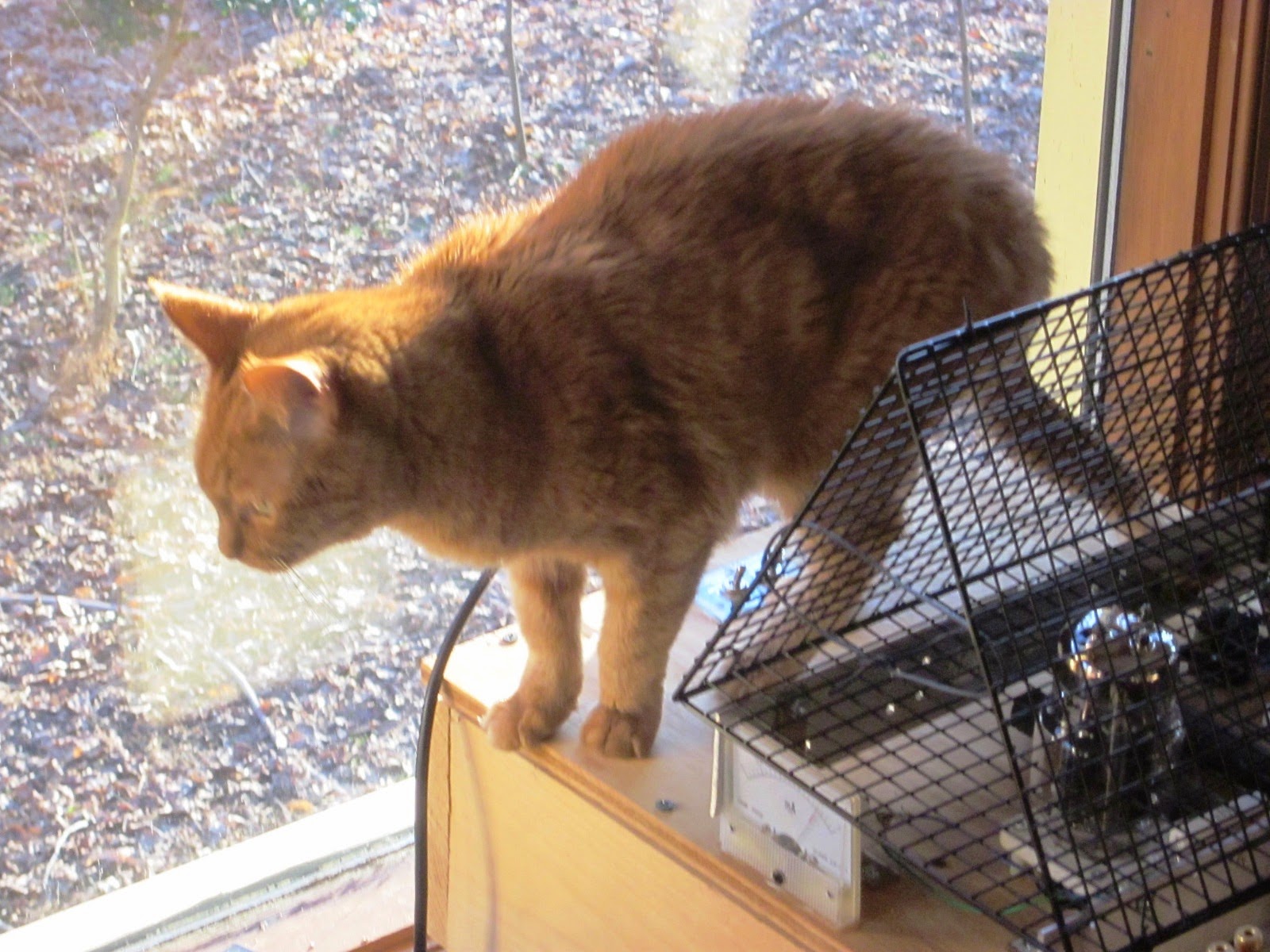
So here is Catty-watty (aka Honey) wandering past the amp. The first time, she looked at it and you could see her wondering 'What the hell is this?'

So the true test of the design is whether it worked. The cat vomited but not in the direction of the high voltage and has lived to meow another day.
Cat Vomits do make me crazy but apparently, I found out a solution here.
ReplyDeleteThis comment has been removed by a blog administrator.
ReplyDeleteThis comment has been removed by a blog administrator.
ReplyDeleteGreat and I have a swell present: How Long Renovate House home remodeling companies
ReplyDelete